Helping out with the design of a giant LED wall at my local hackerspace inspired me to put together something with RGB LED strips myself. After browsing the internet for some inspiration, I decided to build an Ambilight clone.
Hardware
The Ambilight system is basically a strip of LEDs mounted behind a display. The LEDs take on the color of that part of the screen to which they are closest, creating an “aura” of colors. The system was invented by Philips and you can get it on their more expensive range of TVs. The people over at Adafruit created a PC-based clone of this system, called Adalight.
The Adalight system works as follows: software running on the PC analyses the current image and sends color values to an Arduino. The Arduino, in turn, then sends these color values to the LED strip connected to it. This means that you can’t use this system on your TV, since you need to run the software. There’s people that have worked around this by creating the same thing in hardware, i.e. KeiAng’s SCIMO.
An RGB LED strip (anything will do, as long as it’s got individually addressable LEDs), an Arduino and a power supply are all you need hardware-wise to get started. Since I’m using an Arduino Pro Mini, I also needed a TTL to USB converter. All of those can be had very cheap on eBay, I spend less than €20 in total, the power supply I got for free from an old PC.
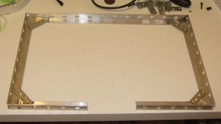
My LEDs strip consists of individual “bulbs”, which has the benefit that I could vary the distance between them to get as uniform a spread as possible. Some leftover aluminum L-profile was the perfect material to create a frame out of. A few hours of measuring, cutting, drilling, filing and epoxying later, I had the perfect housing for my LEDs.

I made a small board to mount the Arduino and USB module on. For my initial design I desoldered the USB plug from the TTL to USB converter and use a long (2-3 meter) long USB cable to the PC. That didn’t work out too well though, because the USB connection kept breaking up. Reversing the system solved the system, I’m now plugging the converter directly into the PC and a long cable is carrying the TTL signal to the Arduino. The whole system is powered with an old ATX power supply, complete overkill, but I had it lying around anyway.
Unfortunately my display doesn’t have a VESA mount, so I would have either had to create some oddball mount system or go for the quick and dirty solution. Well, it’s not like I ever look at the backside of my screen, so I just stuck everything down with tape.

Software
There’s firmware available for the Adalight system, but it didn’t support the UCS1903 driver that’s in the LEDs that I’m using. Luckily, someone already wrote a library that does support that driver though, so fixing the Adalight firmware only involved modifying a few lines of code and including the FastSPI library. You will find the code attached at the end of this post.
On the PC side, there’s a few different software packages that can be used to analyse the screen and sent data to the Arduino. First of all there’s the Processing sketch included in the Adalight system. Unfortunately, it’s quite CPU intensive. Two very good alternatives are Prismatik (formerly known as LightPack) and boblight. I chose to use boblight, which seems to better support for capturing graphics in games, at least in linux.
The final step to getting everything working is configuring the software so that the correct sections of the display are analyzed for each LED. There’s also some color correction parameters that have to be set, so that the LEDs colors match those of your display.
The result turned out pretty good. I find that the effect is quite subtle and immersive, you don’t really notice it’s there until you turn it off, and then you miss it. Ideally the display should be standing in front of a white wall, which isn’t the case for mine. That’s why in the picture below the effect in not as pronounced on the top and right as on the bottom and left.

